Pics or it's all a lie!Originally Posted by EXBEN


Pics or it's all a lie!

and btw nice to see another squirter on here slingy... 88! bah
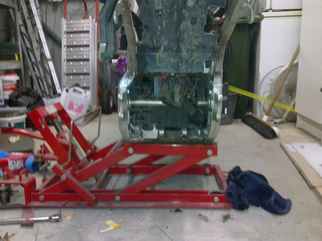
Its just fired back up after the swingarm work to test everything is still ok. It starts great from cold, warms up sweat and is roughly mapped through to about 7000rpm at 10psi. need to get it on the highway then should easliy get the rest tuned. Once i have it tuned at 10psi its disconnect wastegate time for i'm guessing somewhere between 20 and 25psi. The current tables are all set for these pressures and should be easy to foolw the 3D maps to guestimate some good values for these higher boosts, then fine tune them down.
So. in short its ridable, just needs a bit of time riding to autotune it.
what reff do the micro squrit use for the auto tune
Hey surt,
I'll give you a quick run down of the process that i used, but not saying its the best but was what i could do with what i had.
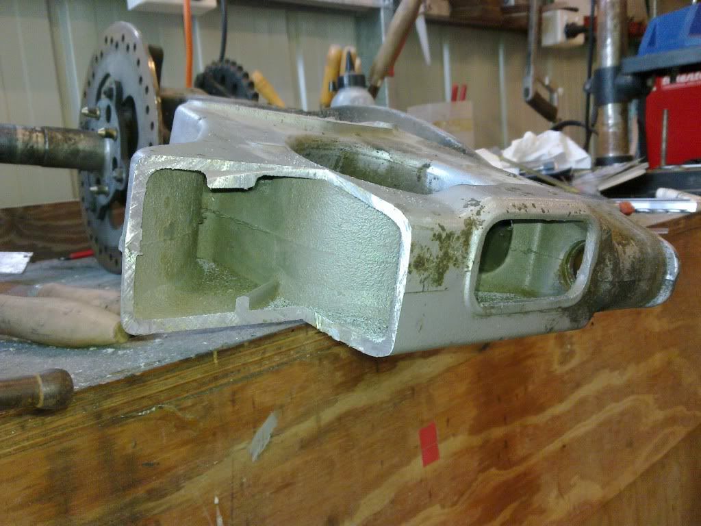
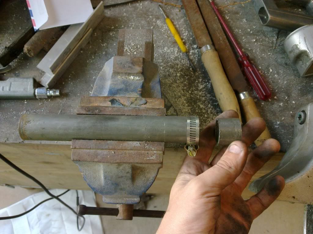
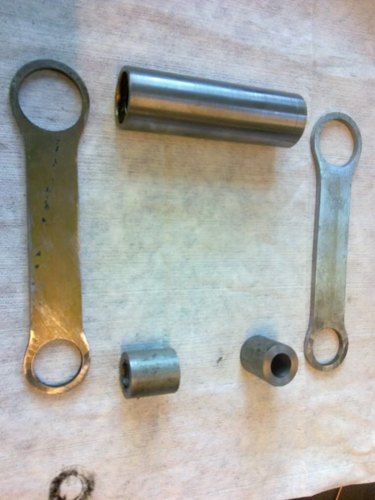
So, to start, slingy is 20mm swingarm spindle and sssa is 25mm, so i decided to use the sssa one as it was just a tube with the ends threaded to take bolts so was easy to shorten to suit, where i would have had to make a whole new longer 20mm one.
so i bored the frame using a 25mm carbide tipped holesaw which give a really clean cut and to make sure it stayed accurate i removed the 5mm pilot drill and machined a new 20mm pilot to fit the frame, stepped down to 5mm to fit the holesaw. This actually worked great but was VERY slow as the teeth kept fouling as there was nowhere for the swarf to go . Probably 45-50minutes per side.
I then thought about the whole Jig or not to jig question and decided i could get away without, mainly because the right side if the frame remains in place the whole time so gives a known point of reference.
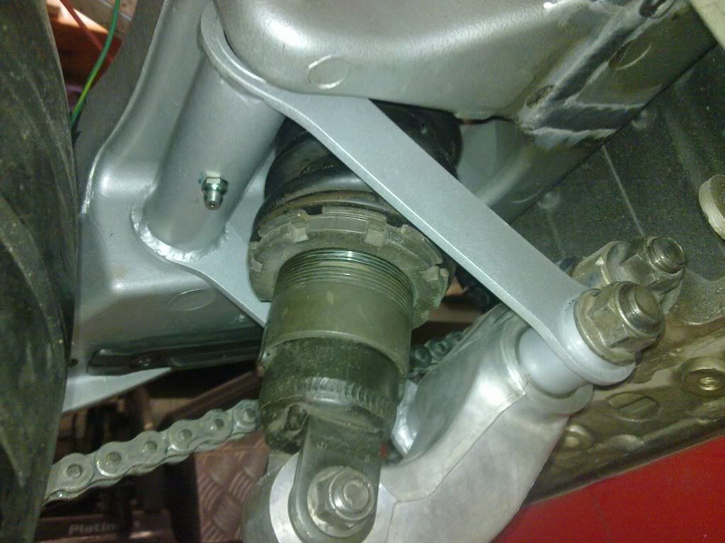
So given the right side of the frame was staying i just decided to witness mark the frame across the cut lines and take measurements from the between the output shaft on the motor and the SSSA spindle, and also from the spindle to the frame cross braces both above and below. This then gave me several ways to cross reference the placement of the moved section of frame.
Then i cut the frame out with a hacksaw to minimise the kurf width, squared the witness marks back across the cut ends so they could be used to line with the origional outer frame marks.
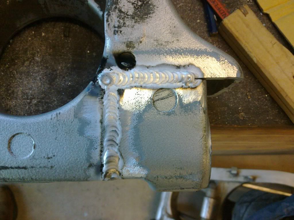
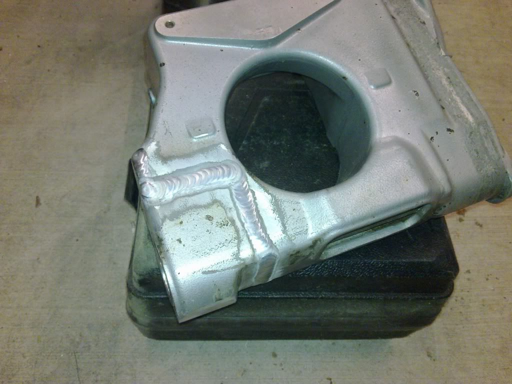
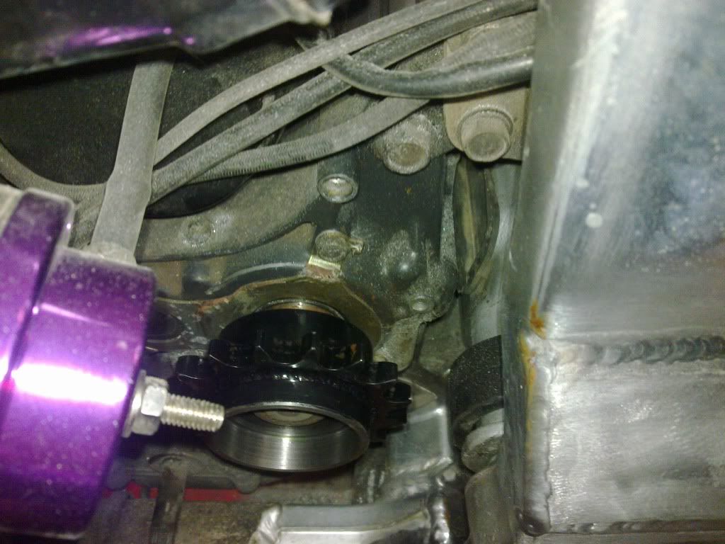
Then, reset the frame offset with the spindle in, lined it all up with the witness marks, cross referenced with the measurements taken off the engine and frame points, then tacked it in, measured again, then pre-heated the whole section of frame with a gas torch before hitting it with the full 215A my TIG can muster.
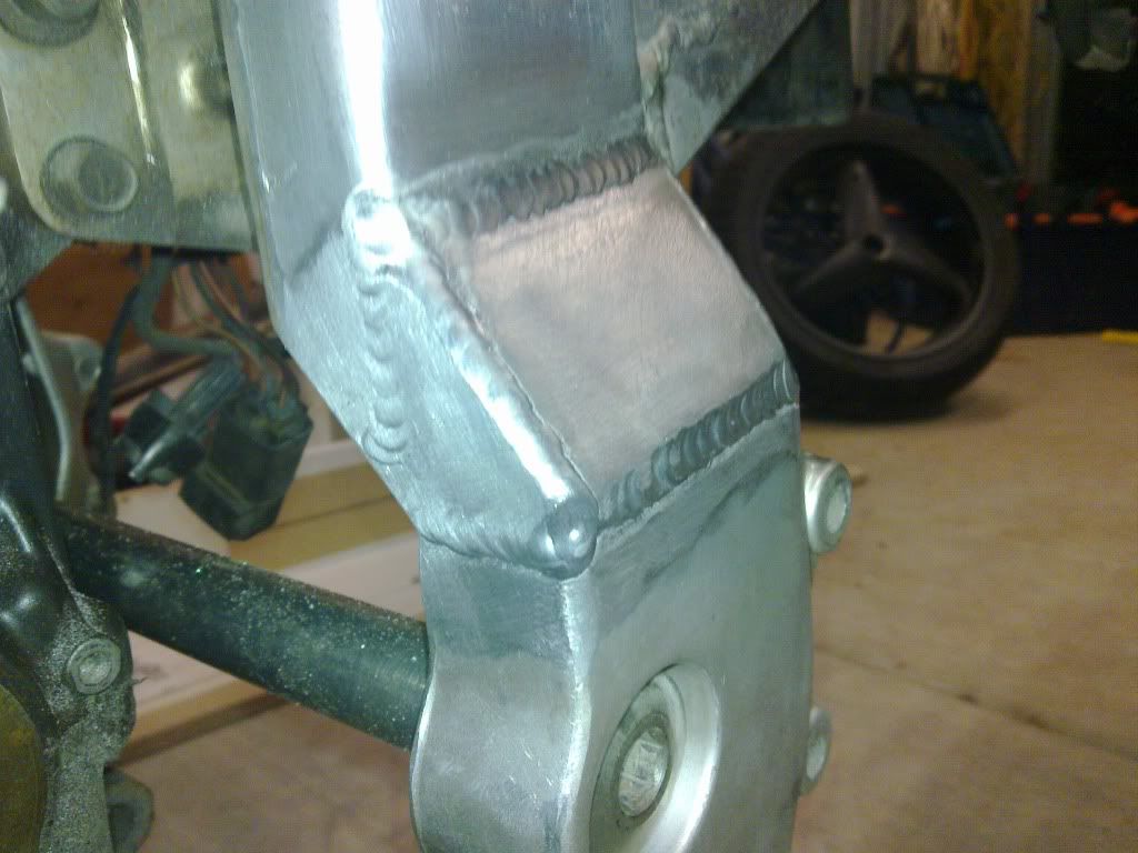
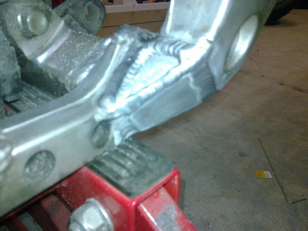
Tripple fillet welds on both sides top and bottom, then plated with 6mm plate over the top to blend the cut edge back into the frame, these were welded with about 165A, all done in one session of welding to keep as much heat in the materials as possible to keep penetration to a maximum.
I'll post all the pictures i have of it, though i dont have any of the cutting as i forgot about the camera for the first bits of the moddding.
Cheers
I LUV my AC tig. Best tool in the shed
I'm running Tunerstudio which has a real time auto tuner built in, so it tunes as you ride, then gives you the option to keep the changes its made to the table or not, lock out parts of the table if your happy with them and various other things. I'm using an Innovate wideband O2 sensor connected to the microsquirt to allow this tuning to work.
i had the choice of my colchester lathe that came up at the right price or a cheep ac and as id never get a colcester for under a grand ever again i took it but still want ac lol
i have dc that i use for s/s fad at work so no big deal
wide band diff the way to go didnt know it worked with the micro squirt very intersting btw the frame work is shit hot
thanks for pics and time spent slingy hopefully u dont need to anneal cast alloy once u pre heated the welded parts
You did well to get a colchester for that price!! My lathe if my second favourite tool, recently upgraded my Myford to this 13x40 machine.


So does the rear wheel sit dead centre after all the work? I guess that was compensated for with the frame and sprocket offset.
must of been adjusted with a spacer just my guess
Yep,it sure does, and like you say thats the whole reason for the frame mod.
Basically, with the wheel fitted to the SSSA i ran a straight edge down either side of the rim and marked these points on the swingarm pivot. The centre of the 2 marks is the centre of the rim at the swingarm pivot and witness marked with the centre punch as this is what everything needs to relate to.
From memory the GSXR arm was 230mm across the pivot, the frame was 235mm gap and the SSSA was 282mm across.
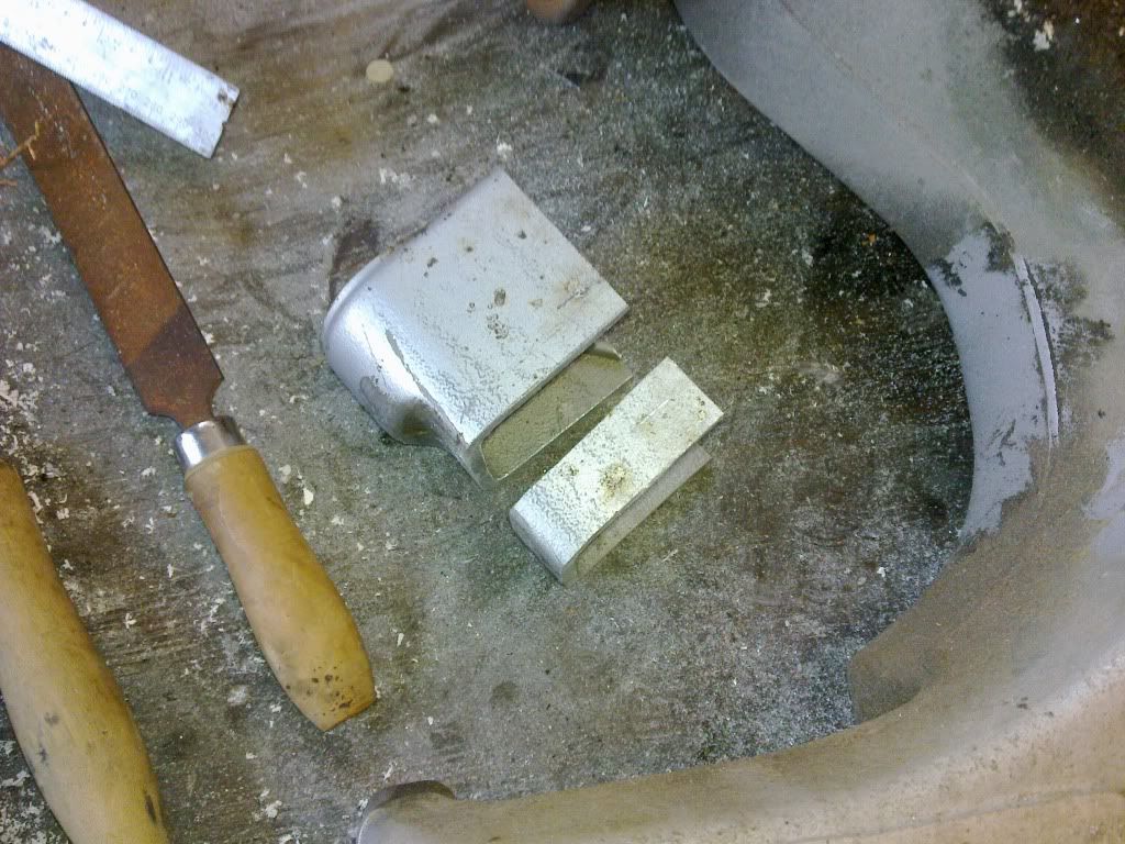
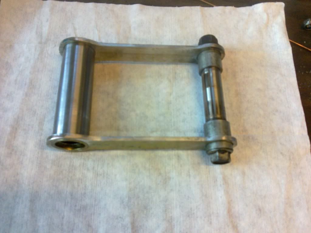
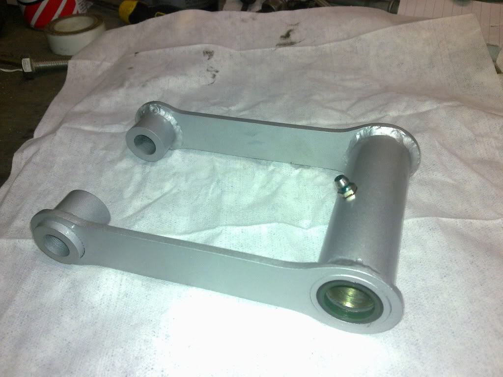
So to make the arm fit, first job was make the right side the same width from the centreline as the gsxr one which would be 115mm. The SSSA was 141mm, so 26mm was removed from this side of the arm and the bearing carrier welded back on to suit, then the excess arm material cut off and the hole plated over with some 6mm plate.
So with the wheel in the centre of the bike the difference between the centreline of the wheel and the inner face of the sprocket carrier between the GSXR and the SSSA was 17mm. (This was also double checked once the arm was in by holding a straight edge up against the rear sprocket and measuring the gap between it and the front one which it was. This was good as if the arm was pissed one way or the other in the frame, this measurement would have been affected.)
So there was no way to cheat it, you cant machine the carrier down, the frames not thick enough to grind a bit out, so the only option was to do the frame mod. What it does mean though is that the wheel, and sprocket carrier assembly etc are stock .
Hope that helps a bit
Yea mate, Ben did the exact same mod to my frame, that's why I recognised what you had done, but just wanted to confirm it was for that reason.
Any chance of a couple of close up shots of your frame to compare how a pro has done it?
heres a quick Video of the first time the bike fired up on microsquirt, just on a map i guessed at on the kitchen table.
We'll have to hope Ben sees this post as he still has the bike and the photos currently.
Thats awesome as fuck! Nice work mate!
 Posting Permissions

 Reply With Quote